 Placing equipment racks
|
Tool |
Workspace: Tool set |
|
Equipment Rack 3D
|
Design Suite and Spotlight: ConnectCAD Layout ConnectCAD: Layout |

A 3D equipment rack represents a stand-alone, 3D view of a rack, console, or enclosure for a concept drawing or a model view of the design.
An equipment rack can connect to a cable network, and is considered to be a drop point; the connection occurs at the center rear of the rack. To connect rack-mounted equipment to a cable path network, connect the rack.
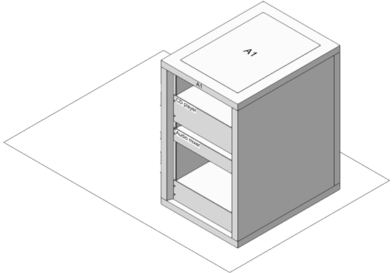
Equipment and rack frames placed within a rack are associated with that rack for display, identification, and reporting purposes, and move with the rack.
To place an equipment rack:
If you are using the optional ConnectCAD template, ensure that the current design layer is Rack 3D Layout. This coordinates with the view settings for the design layers and the viewports on the sheet layers, for proper display.
Click the tool.
Click to place the equipment rack. The first time you use the tool in a file, a properties dialog box opens. Set the default parameters. The parameters can be edited later from the Object Info palette.
Click to show/hide the parameters.Click to show/hide the parameters.
|
Parameter |
Description |
|
General |
|
|
Rack ID |
Enter an identifier for the rack; equipment and rack frames placed in the rack inherit this ID as a read-only parameter that identifies their location |
|
Make/Model |
Enter the manufacturer's make and model information |
|
Configuration |
|
|
Rack Opening |
Select a standard rack opening width, or select Custom to open the Set Custom Opening dialog box and enter a custom width. To fit into the rack opening, equipment cannot be wider than this value. Changing this parameter adjusts the Width (overall) and maintains the Post Width. |
|
Height |
Select the mounting area height in rack units. If Allow half rack unit mountings has been selected on the General Settings pane of the ConnectCAD Settings dialog box, you can also select half-rack units. (See Specifying ConnectCAD settings.) If the Rack Style is Enclosure, the height displays in document units. Changing this parameter also changes the Height (overall) of the rack and maintains the Top Thickness and Base Height. |
|
Depth |
Enter the rack’s size. Changing this parameter adjusts the Depth (overall). |
|
Rack Style |
Select the rack type: Rack (4-post) Rack (2-post) Console Enclosure: Equipment placed in the enclosure aligns to the front or the back, but does not snap vertically. Horizontal placement is limited to the enclosure bounds. |
|
Console Slope (Console Rack Style only) |
Enter the slope value in degrees |
|
Panel Thickness (Console Rack Style only) |
Enter the thickness to model the cladding surrounding the panel |
|
Physical |
|
|
Height (overall)/ |
Enter the dimensions of the rack in document units. Changing the Height (overall) adjusts the mounting area Height to the nearest rack unit; the Base Height compensates for any remaining difference. For the enclosure style, the mounting area Height will be the Height (overall) minus the Top Thickness and Base Height. Reducing the Width (overall) reduces the Post Width and sets the Rack Opening to a lower value, which readjusts the Post Width. |
|
Post Width/ (Post and Enclosure Rack Style only) |
Enter the dimensions of the posts. Changing the Post Width adjusts the Width (overall) and maintains the Rack Opening. |
|
Top Thickness (Post and Enclosure Rack Style only) |
Enter the thickness of the top of the rack. Changing this parameter adjusts the Height (overall). |
|
Base Height (Post and Enclosure Rack Style only) |
Enter the height of the base of the rack. Changing this parameter adjusts the Height (overall). |
|
Power Consumption (W) |
Displays the total power requirement of the rack and the equipment it contains |
|
Weight of Rack (kg) |
Enter the weight of the rack only |
|
Total Weight (kg) |
Displays the total weight of the rack plus the equipment it contains |
|
Options |
Select the portions of the rack to draw in 3D; drawing more parts will look more realistic, but take longer. Classes are created for each included part to further control visability and display. Covers and doors are disabled for 2-post racks, and rulers are disabled for enclosures. |
|
Location |
|
|
Room ID |
Specifies the room ID, if the equipment rack is contained within a layout room (see Creating a layout room). Changing the value moves the rack into a different room. |
Viewing front and rear mounted equipment
Some equipment is mounted to the front, and some to the rear, of the equipment rack, based on the Mounting selection in the Object Info palette of a selected device. For times when you need to see only equipment mounted in the front or rear configuration, use the CC-Equipment-Front and CC-Equipment-Rear classes to control the visibility of the equipment.
In a viewport, accomplish the same effect by using viewport class overrides to control the visibility of the CC-Equipment-Front and CC-Equipment-Rear classes in the viewport.
Creating rack elevation viewports
|
Command |
Workspace: Path |
|
Create Rack Elevation |
Design Suite: Entertainment > ConnectCAD Layout Spotlight: Spotlight > ConnectCAD Layout ConnectCAD: ConnectCAD > Layout |
The Create Rack Elevation command creates a sheet layer with section viewports that display the front and/or rear views of selected racks or contiguous groups of racks.
To create a rack elevation section viewport:
Select one or more racks, and then select the command. If you select multiple racks that are not contiguous, the command creates a separate viewport for each rack.
The Create Rack Elevation dialog box opens.
Click to show/hide the parameters.Click to show/hide the parameters.
|
Parameter |
Description |
|
Sheet Layer (Destination) |
Select the sheet layer for the rack elevation viewport |
|
Viewport Name |
Specify a name for the viewport |
|
Views to Create |
Select which views to create: Front: /F is appended to the name of a front view. Rear: /R is appended to the name of a rear view. Select both options to create front and rear views. |
Select the sheet layer for the viewport, or select New Sheet Layer to create a sheet layer; specify a viewport name, and select which views to create.
The rack elevation section viewport is created.
![]()